

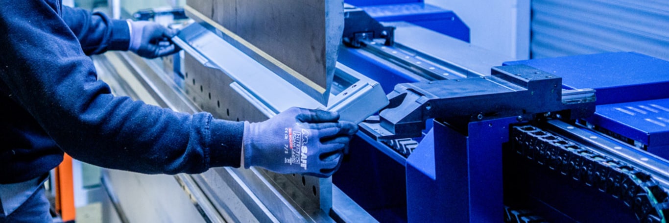
Press brake bending
Sheet metal bending, also called folding or brake forming, is an industrial sheet metal operation in which flat sheet metal parts are accurately bent with a CNC press brake.
Bending typically takes place as the second metalworking operation: after punching or laser cutting, and before fitting, (spot) welding or powder coating.
Looking for a reliable supplier of bent sheet metal parts? Contact us right away!
+31 (0)543 54 67 89 Request a quote
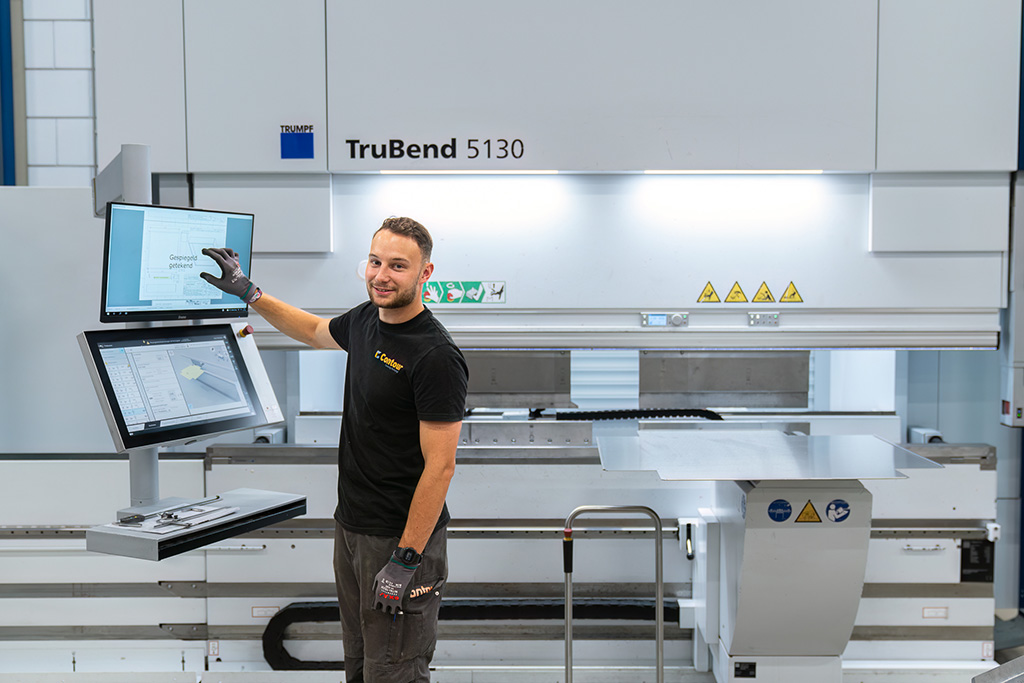
Video of bending
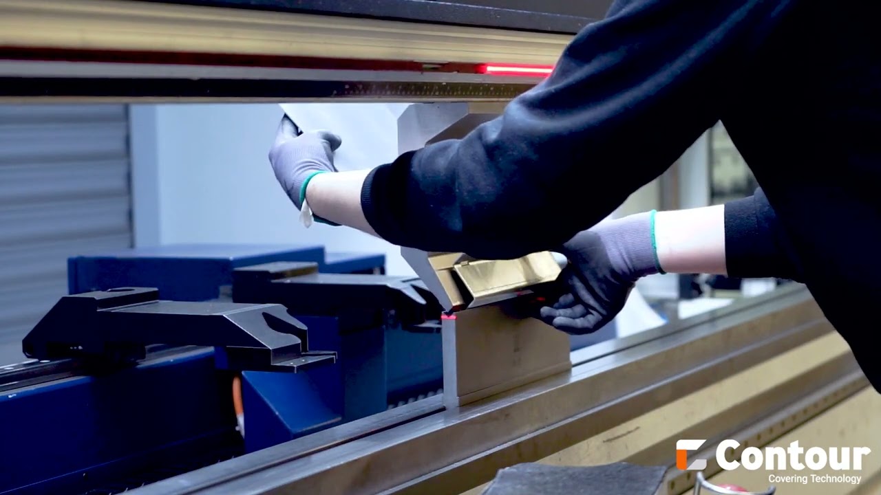
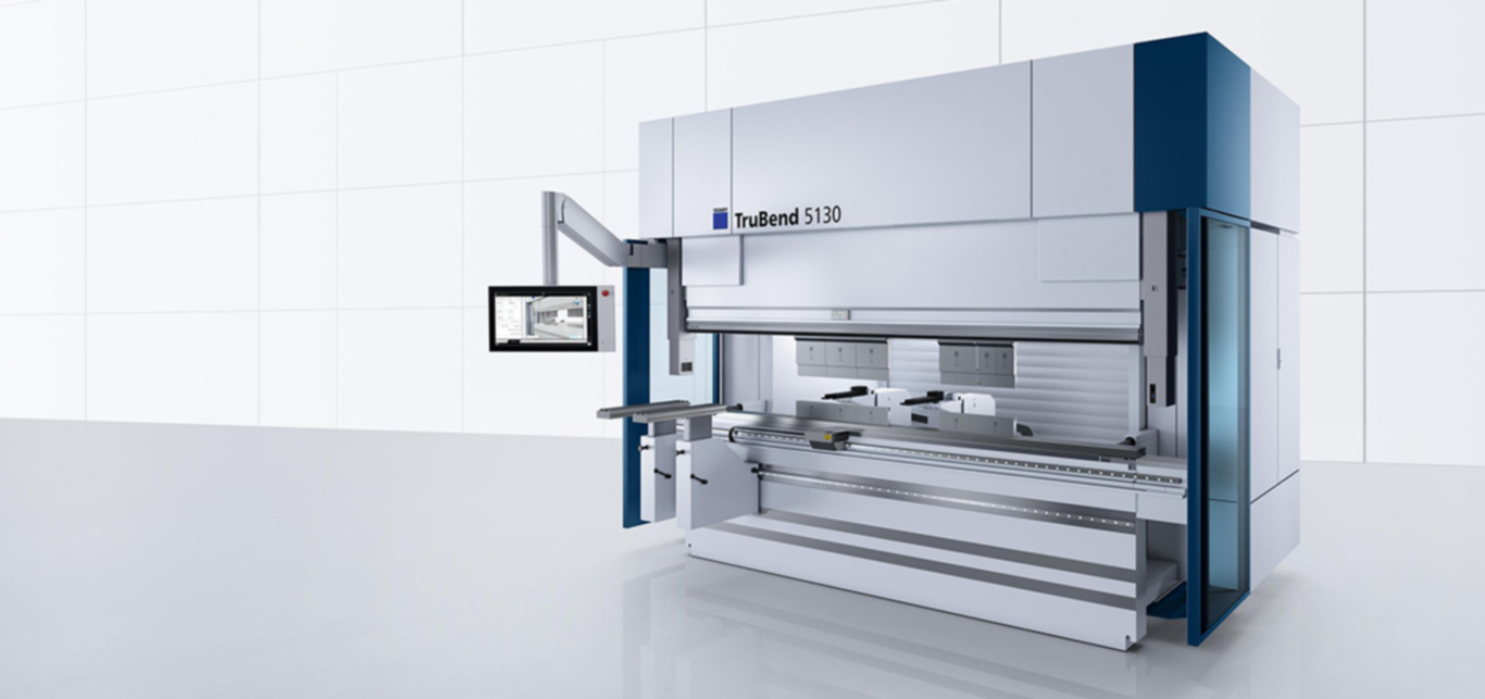
The press brake
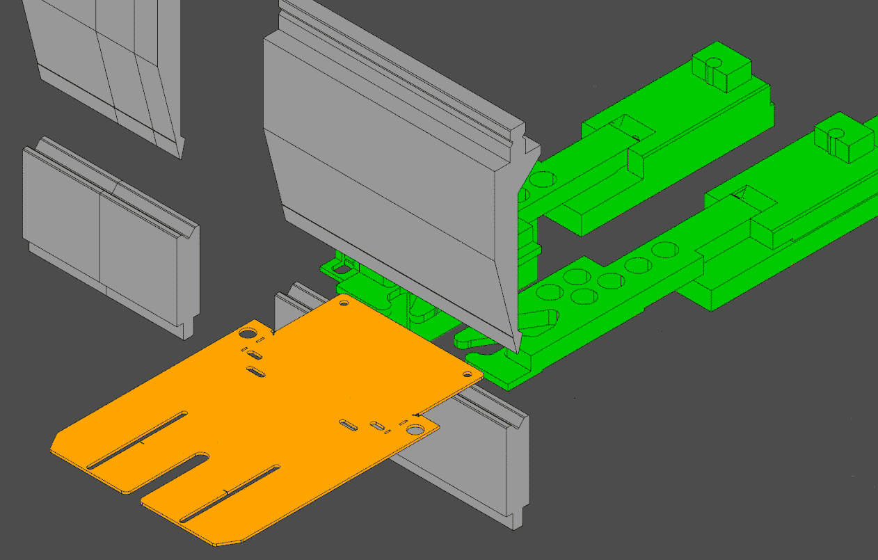
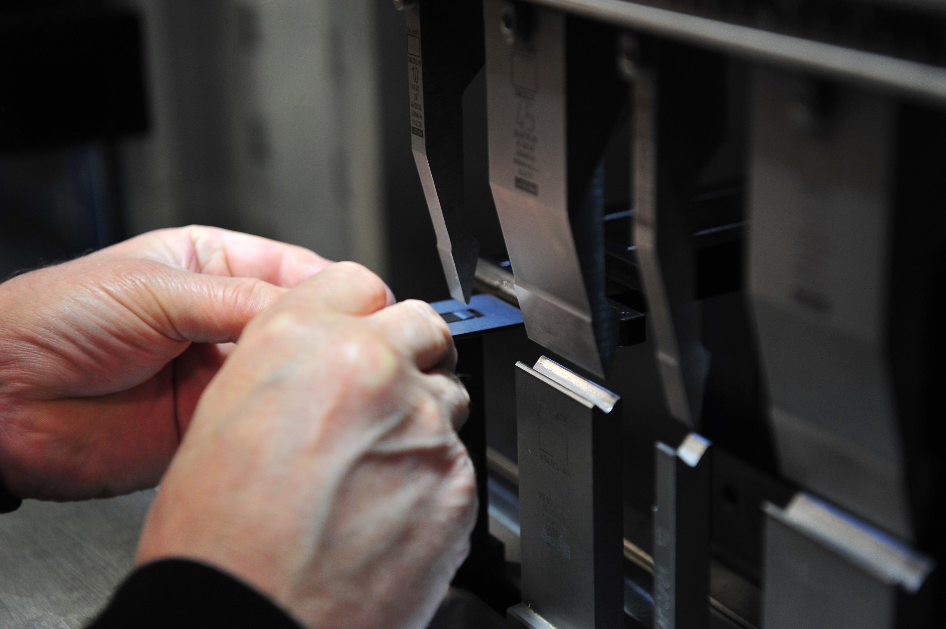
A press brake is a machine used to bend sheet metal. A press brake is a precise hydraulic or servo-electric press. Two interchangeable tools are mounted in this press, and the sheet metal parts are bent between them when the press closes. We call the upper tool the bending tool, and it is wedge-shaped. We call the lower tool the die. The die has a V-shaped or U-shaped recess in the top of the tool.
The bending process
When bending, the flat sheet metal part is placed on top of the die while the operator presses it against CNC-positioned back gauges. This positions the part to be bent accurately during bending. The press then moves the bending tool down along a vertical axis, so that the bending tool is pressed into the recess of the die.
The bending tool applies a point load to the sheet metal part lying on the V-shaped recess. This creates a bending moment on the sheet. In the bending zone, the material is deformed beyond its yield strength.
Free bending
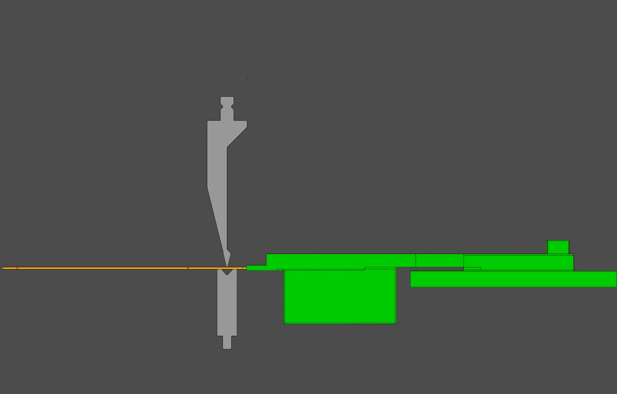
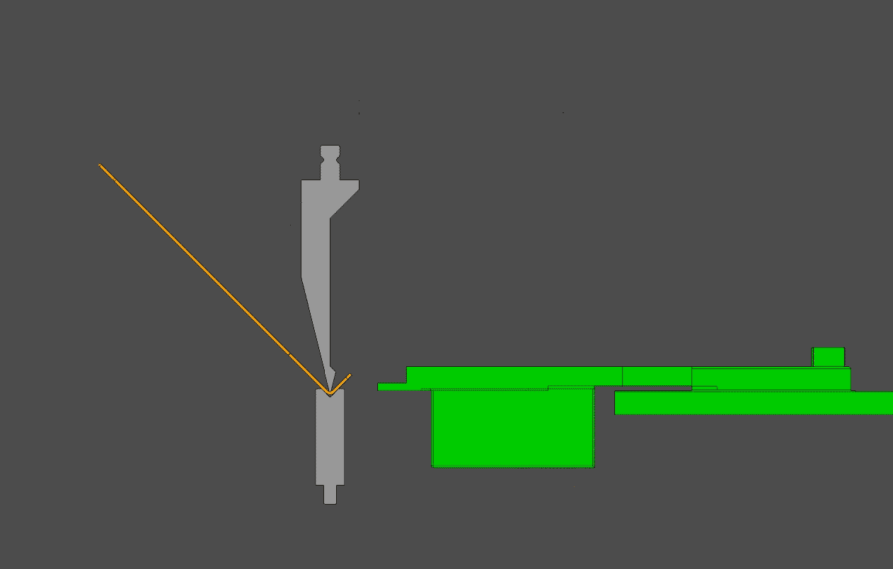
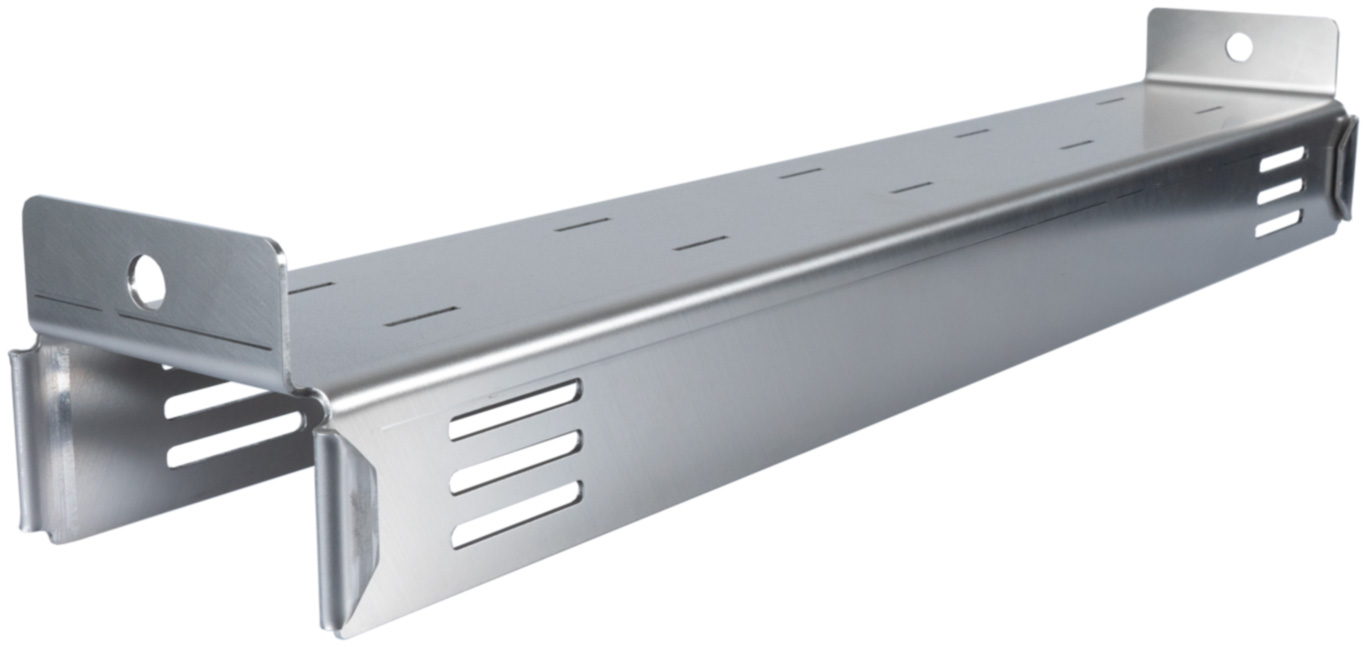
In free bending, the bending tool moves during the press stroke to a CNC-controlled Y coordinate (depth). When the bending tool moves back up after bending, the sheet metal is permanently deformed after a slight springback. The bending tool moves down exactly as far as the point where, after springing back, the desired angle is reached. In free bending, the press brake therefore does not press the material completely into the bottom of the die. An advantage of free bending is that different angles can be bent with a single bottom die. The tonnage required from the press brake is also lower than in bottoming, so the bending tool leaves less of a mark on the surface of the sheet.
Bottoming
In bottoming, the sheet is pressed with force into the bottom of the die during bending. In jargon, we also call this technique ‘coining’. The resulting angle is then exactly equal to the angle of the V-shaped recess in the die. The sheet is pressed into the die with so much force that all internal stress in the material is neutralized. The material then no longer springs back and has taken on the shape of the die.
Bend deduction
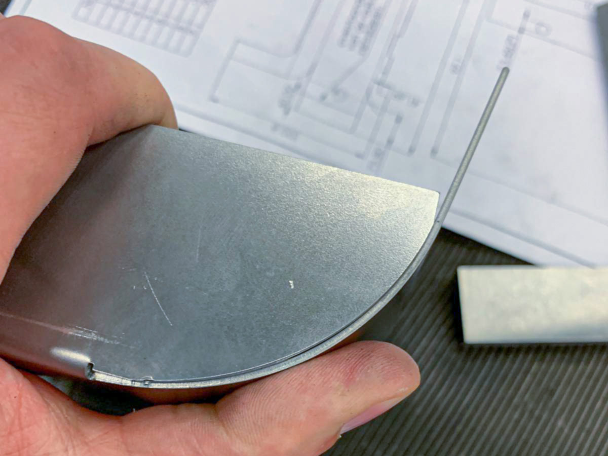
It is important to know that the curvature of a sheet after bending does not describe an arc with a perfectly constant radius. The curvature on the outside of the bend is also not perfectly concentric with the curvature on the inside of the bend. This means that the center points of the two radii are not in the same place.
This is the result of how stress builds up in the sheet during bending. When a sheet is bent, the material on the inside of the bend is compressed. The material on the outside of the bend is stretched. During bending, the material on the outside stretches more than the material on the inside can compress. Factors such as the coefficient of friction between the material and the die also play a role.
To achieve the leg lengths of a bent sheet accurately, the length of the flat pattern of the sheet (the unfolded product) must be determined before bending. Because of the effect above, it is not enough to simply determine the length of the neutral line of the bend in the sheet (based on the average of the outer and inner radius).
There is a formula to determine the correct, corrected neutral line after bending using the so-called K-factor. However, this does not give an accurate end result. The most reliable way to determine the correct dimension of the flat pattern is by using values measured in practice. The so-called bend deduction can be calculated from a sheet that has been bent in practice. The bend deduction can be used to calculate the length of the flat pattern of the sheet. The bend deduction is therefore used to calculate the length of the flat pattern, instead of a formula that describes the neutral line of the sheet.
The bend deduction can be defined as follows: it is the difference between the sum of the leg lengths up to the outer dimensions of the bent sheet (assuming a perfectly sharp angle instead of a bend radius) and the length of the unfolded flat sheet. The bend deduction is the number of millimeters you must subtract from the summed length of the bent legs, measured at the outer dimensions, when calculating the flat pattern.
Contour has built up an extensive database of all common material and tool combinations. For all of these combinations, the bend deductions have been entered into a CADCAM database in an ingenious way. Using this database, we can determine the correct flat pattern for every desired angle.
Bend radius
By varying the radius of the tip of the bending tool and the opening of the die, the size of the bending zone, and with it the radius of the bend line in the sheet material, can be influenced. If a larger radius is desired, step bending can be chosen instead of a single bend. In step bending, several bends of only a few degrees are actually made next to each other until these bends together produce the desired angle.
Although there are formulas to approximate the curvature, empirically measuring the bending result turns out to be the only truly accurate way to establish what the end product will look like. At Contour, we have therefore scanned and measured the resulting bends for all common materials and tool combinations. With this data, it is possible to engineer sheet metal products accurately with short lead times. After these products are bent, the bend connects seamlessly to the adjoining products. In TIG welding, the parts can therefore often be ‘flowed’ together without adding filler material.
Bending FAQ
What is bending?
Bending, also called folding or brake forming, is a sheet metal operation in which sheet metal is bent with a press brake.
A press brake is a precise hydraulic or electric press. An interchangeable upper and lower tool are mounted in this press. We call the upper tool the bending tool. The lower tool is a die.
The die typically has a V or U shape. The material to be bent is placed between these tools. The material is positioned accurately with a CNC-controlled back gauge. The bending tool then pushes the sheet material into the die until the desired angle is reached.
The video below shows what CNC bending looks like in practice.
What is a press brake?
A press brake is a machine used to bend sheet metal. It is a precise hydraulic or servo-electric press with two interchangeable tools, the bending tool and the die.
What is free bending?
Free bending is a bending technique in which the bending tool moves to a certain depth during the press stroke, without the material making full contact with the die. (There is therefore space between the bottom of the die and the material.) The sheet metal remains permanently deformed after bending, following a slight springback. The advantage of free bending is that different angles can be bent with a single bottom die and that less tonnage is required, so the bending tool leaves less of a mark on the surface of the sheet.
How does bending work?
When bending, the flat sheet metal is placed on the die while the operator presses it against CNC-positioned back gauges. The press then moves the bending tool down, pressing it into the recess of the die. The bending tool applies a point load to the sheet metal, which creates a bending moment and deforms the material.
What is bottoming?
Bottoming is a bending technique in which the sheet is pressed against the die with force during bending, also called ‘coining’. As a result, the resulting angle is exactly equal to the angle of the V-shaped recess in the die, and the sheet takes on the shape of the die.
What is bend deduction?
Bend deduction refers to the difference between the sum of the leg lengths up to the outer dimensions of the bent sheet (for a perfectly sharp angle) and the length of the unfolded flat sheet. During bending, the material is compressed on the inside and stretched on the outside, so the curvature of the sheet is not perfectly constant. The bend deduction must be subtracted when calculating the flat pattern of the sheet.
What are the main factors that affect the quality of bending?
Important factors that affect the quality of bending include the right choice of bending tool, the quality and thickness of the sheet material, the precision of the CNC press brake, and the skill and experience of the operator.
Can every type of sheet material be bent?
No, not every type of sheet material can be bent. Thin sheet materials such as aluminum, steel, and stainless steel can usually be bent without problems. However, some materials have specific properties that require extra attention when bending. For example, the radius being bent must be taken into account, and aluminum can crack if the angle is set too sharp. Based on our experience, we can assess whether your product can be bent and advise you on manufacturability.
How accurate is sheet metal bending?
The accuracy of sheet metal bending depends on several factors. In general, sheet metal can be bent with an accuracy of a few tenths of a millimeter (depending on sheet thickness and length). When the leg length is not too large, we can bend with a tolerance of 0.2 mm. When designing a part to be bent, you must take into account a tolerance that builds up when several bends are made in succession. When the important dimension is measured ‘across’ several bends, this affects the dimension that can finally be achieved. Contact us for more information.